Chapter
1
Powering the
LED
The best place to start is to just make one single LED light up. In
this chapter we will look at the three components necessary to do this:
the LED, the resistor, and the battery.
Please do
not connect the LED directly up to a 9v battery, there might be a
slight flash, but then the LED won't work ever again.
LEDs can handle only a limited amount of current. An LED can last for
longer than you will live, when you use it at it's rated current, or it
can be blown up in an instant if the current is not controlled.
LEDs that are in flashlights are usually specially designed to run at
the same voltage as the battery. It can be difficult to find these LEDs
sold separately, so replacing the LED in a flashlight can be
problematic.
The most common way to limit
the current
in an LED is by using a resistor. Resistors come in various shapes and
sizes, but nearly all of them have a wire or a pad on each side. The
more modern resistors are tiny flat pieces of ceramic that solder
directly onto a printed circuit board.
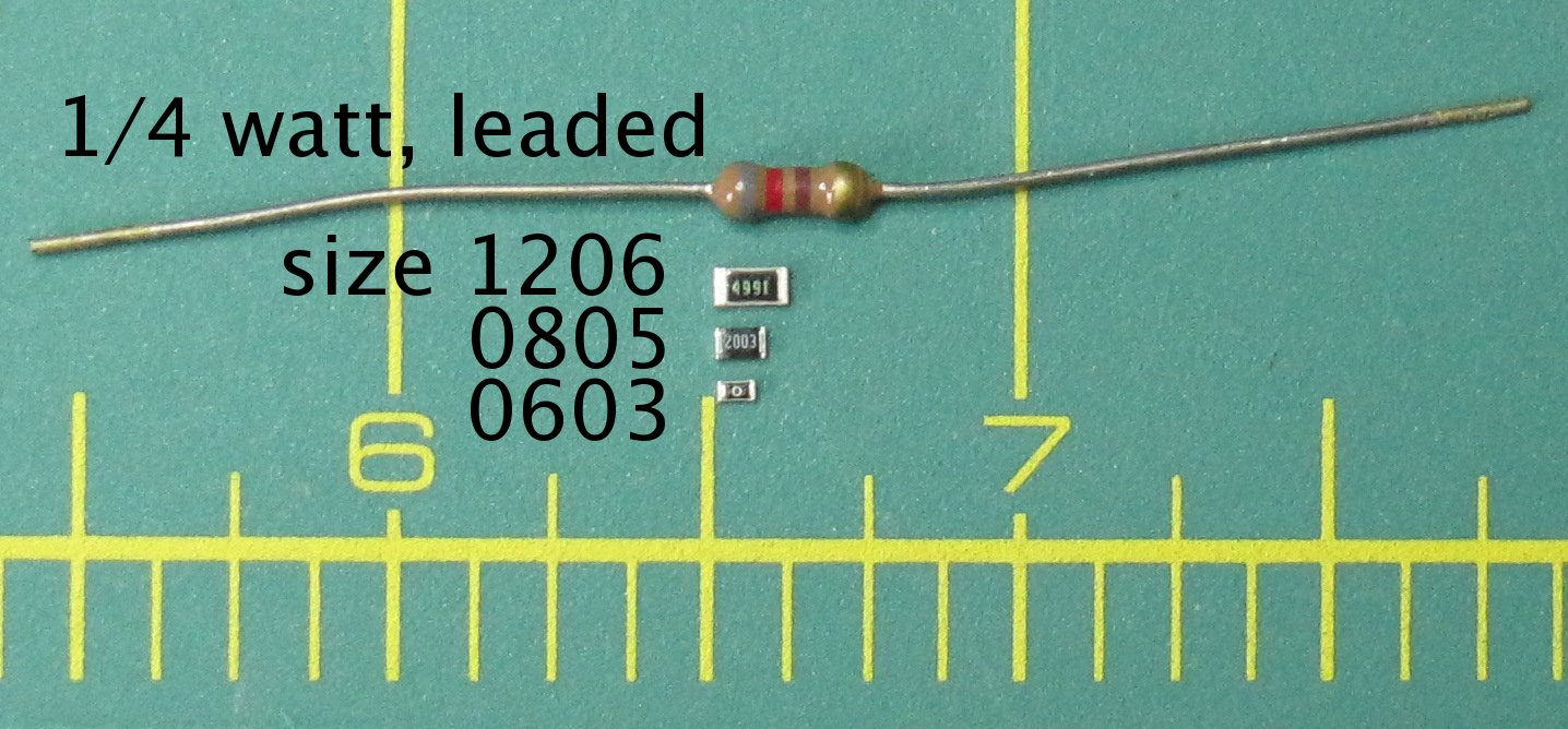
Some
resistors are larger size so that they can convert more power into heat
without over-heating. When the resistor has more surface area exposed
to the air, more power can be converted into heat without the
temperature of the resistor becoming too high. Resistors have a power
rating in watts. This rating is usually for when the resistor is used
at normal room temperature.
The resistor needs to
be a
different value depending on the voltage and the amount of current that
the LED was designed for. You may choose the perfect value of the
resistor by using a math formula that will be explained later. The
smaller the value of the resistor, the brighter the LED will be. If the
resistor value is too small, the maximum rated current for the LED will
be exceeded and it will burn out. If the resistor value is too large,
the LED will be really dim.
Nearly all
LEDs will light up with the following resistor values:
3v 300
ohms, 5v 500 ohms, 9v 900 ohms, 12v 1200 ohms, 24v 2400 ohms.
There is a pattern here. Just add two zeros to the voltage, choose that
value of resistor, and you can safely test out nearly any LED to see if
it is working. This is a safe current for all but the really tiny, or
super low current LEDs. The LED will not be very bright, but you will
be able to easily see it light up. LEDs only light up when the polarity
is correct. This means that you might need to reverse the connections
to the + and – side of the LED if it does not light up the
first
time.
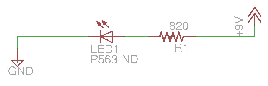
This is a schematic of the circuit
that we will be building:
So lets hook one up and see it light up. If you are familiar with
soldering and hooking up LEDs, you may want to just skip to the next
chapter.
We will start with the tools that you will
need:
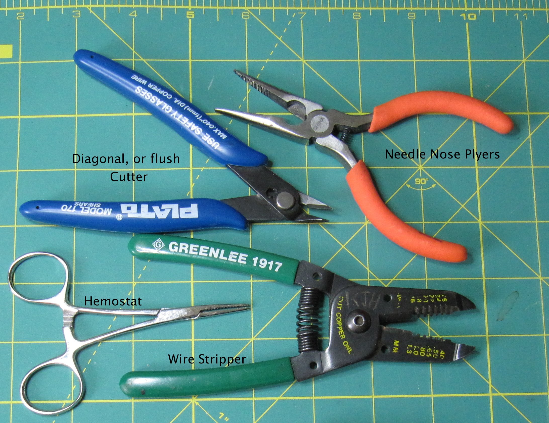
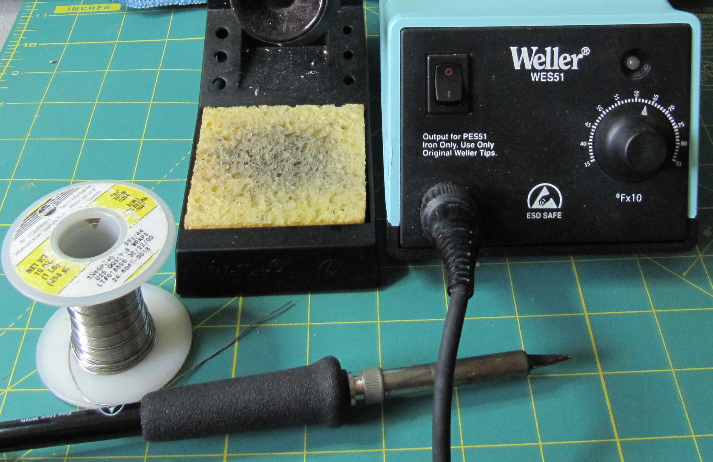
The Weller is nice, but if you are just starting out, a 15 watt
soldering iron from Radio Shack, or Ebay will do just fine.
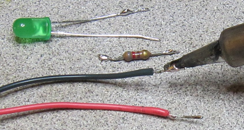
Here is a picture of the
parts:
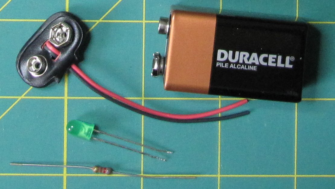
The resistor is an 820 ohm. For a 5% resistor close to 900 ohm, we have
a choice between 820 and 910 ohms. The reason is that the resistor
manufacturers used to arrange the selected values so that any possible
resistance value would fit into at least one salable value. In this
way, there were no wasted resistors, even though the process control
was a bit lacking.
First thing to do is
to strip the wires on the 9v connector:
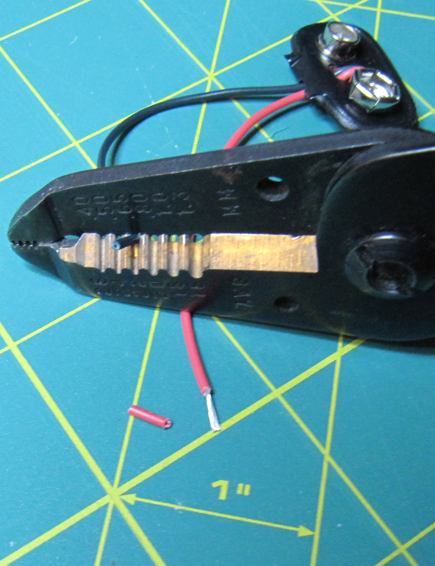
Using the wire stripper requires the selection of the correct position
for the wire size, then you place the wire into the stripper, clamp it
shut and pull the wire. The pulling part can be problematic because
sometimes the stripper will grab the wire and pull it out of the
insulation. This usually happens when the wire length is short. This
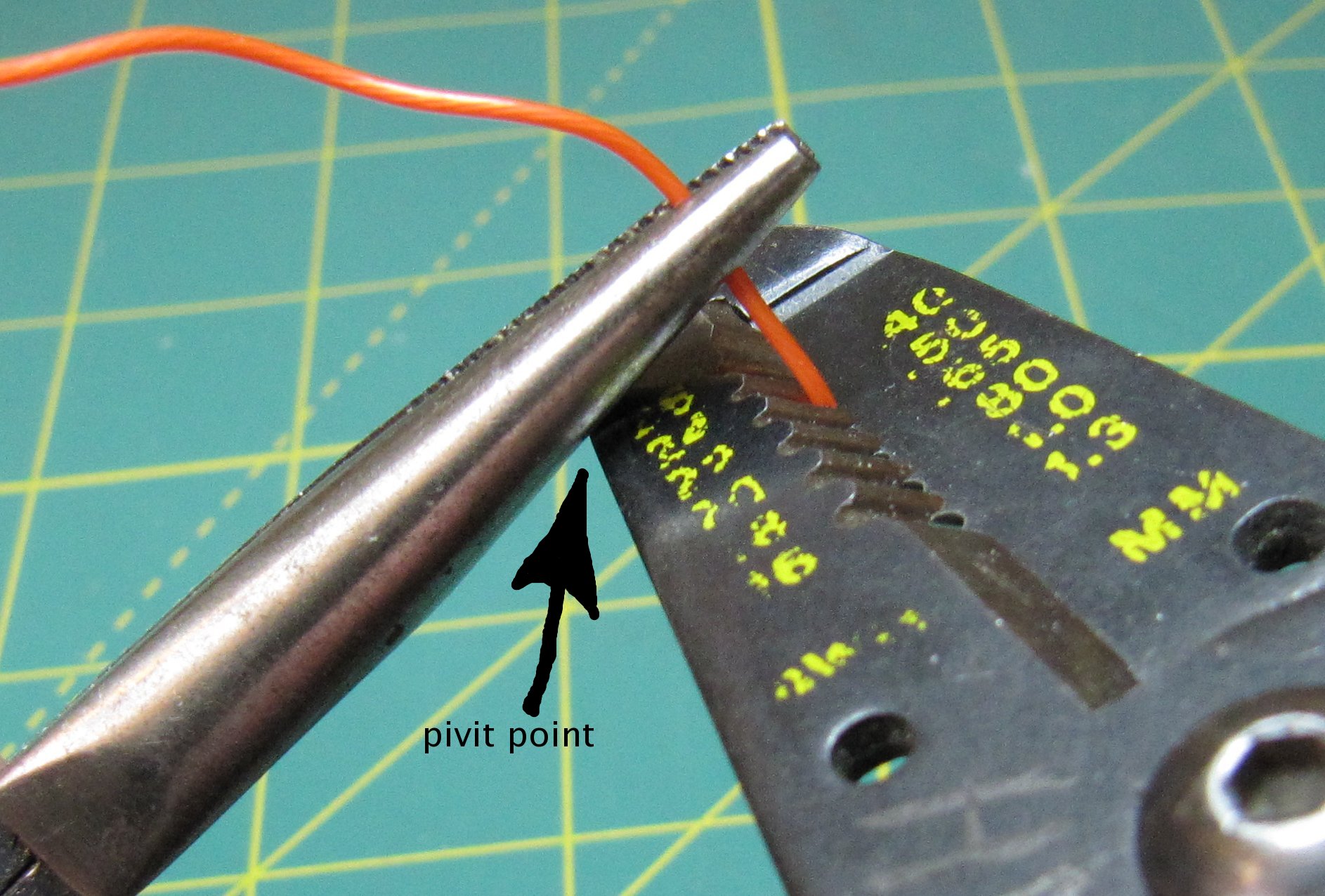
problem can be avoided by holding the wire with needle-nose pliers. The
pliers will compress the insulation enough that both the insulation and
the wire will be pulled out of the stripper at the same time. If you
grab the wire close to the stripper with the needle-nose pliers, you
will be able to lever the pliers against the stripper. The wire will
now come out of the stripper smoothly with no lengthening of the
stripped part verses the insulation.
After you have stripped a wire, it is a good idea to look at the end
with a magnifying glass and see if you have cut off some of the
individual strands of the wire. If there are a few strands left in the
removed insulation, the wire should be trimmed and stripped again while
using one of the larger sized positions in the wire stripper. If there
are missing strands, chances are good that the other strands are
damaged and will soon break. Damage to a strand would be any cut mark
(visible using a microscope). When the wire is bent back and forth
during normal use, any cut will get larger until the wire breaks.
Next, we will put some solder onto all of the leads. This is called
“tinning” the leads.
The solder should be shiny and it should look like it has flowed evenly
onto the leads (concave fillets). If the solder looks like a small glob
that just dropped onto the lead, you can try melting the solder at the
same time as the tip of the soldering iron is touching the lead. The
smoke that rises from the solder is the flux burning. The flux cleans
the surface of the wire so that the the solder will attach to the wire
and flow over it, thus making a good connection. Once the flux has
burned away, more flux may need to be applied in order for the solder
to flow onto the surface of the wire. A clean tip is also necessary.
Wet the sponge and rub the tip of the iron on it for just a short
second. You should hear a hiss as the tip turns a bit of the water on
the sponge into steam. Add some solder to the tip and then rub the tip
on the sponge again. The tip should be really shiny after this.
Soldering is pretty important, so it is a good idea to do a web search
for soldering (wikipedia is a good place to start). There are
many courses and web pages that have been written on soldering.
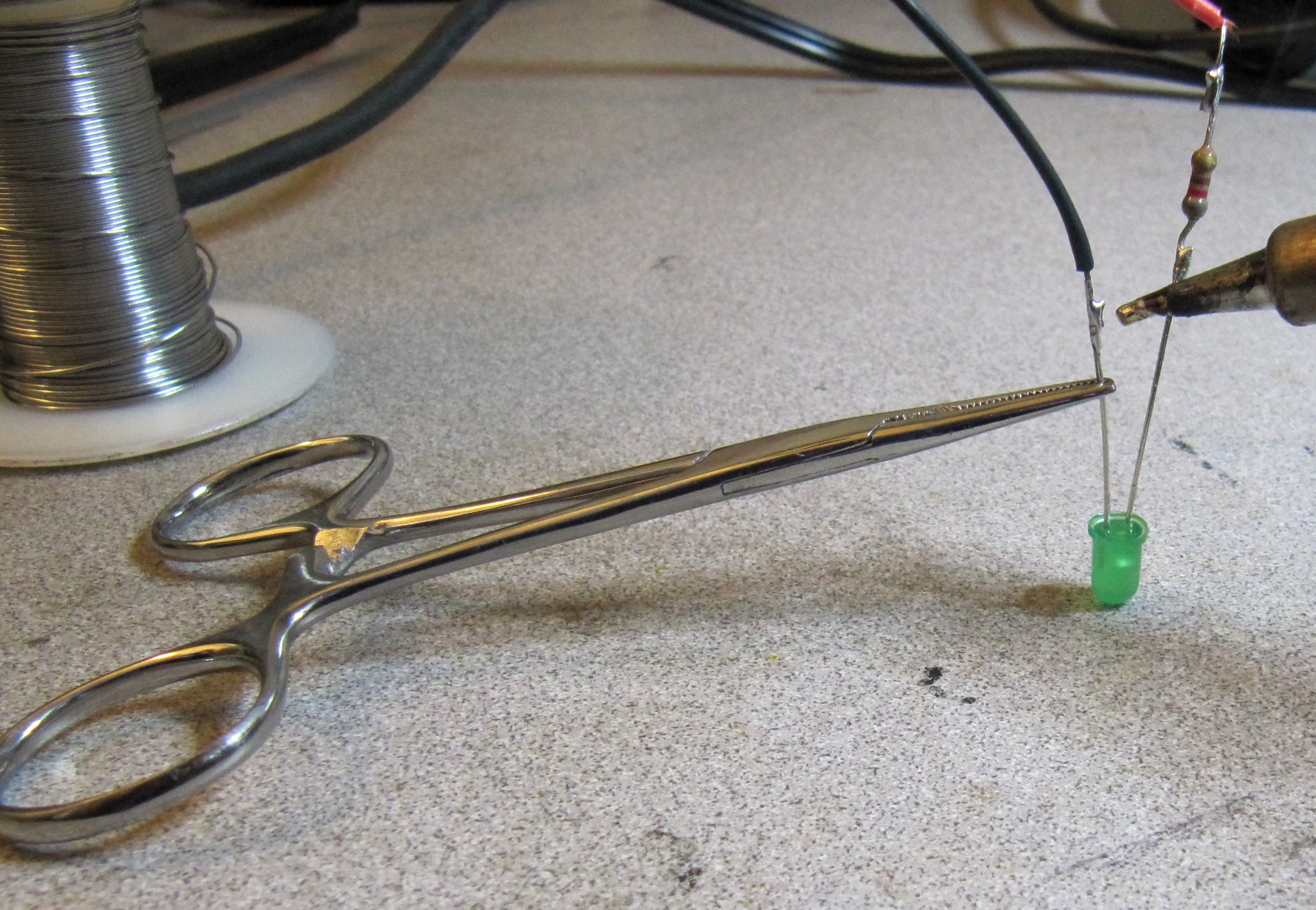
Now we are ready to solder the parts together. Be sure that the longer
lead of the LED is connected to the resistor, and that the resistor is
connected to the red wire. The side of the LED that is flat should be
connected to the black lead.
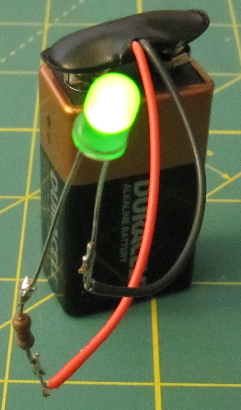
The LED is now ready to test. Be sure to keep the leads from touching
each other. Electrical tape or heat shrink tubing may be put on the
leads to keep them from touching, but this is a demonstration, so I
left the leads so that all of the connections may be seen. If the
exposed conductor of the red wire were to touch the exposed conductor
of the black wire, the battery would become drained and possibly
overheat. A shorted battery can leak toxic chemicals and a few high
power batteries can actually explode, depending on the type of battery.
A car battery could cause the wires themselves to turn red hot and this
would seriously burn your hands if you were holding the wire at the
time.
If you are interested in how LEDs are made and why they light up, there
are many pages on the web. One good place is: LightEmittingDiodes.org
There are many theories about why LEDs work, but these theories were
not used to make the first LED. The first LED was discovered by H. J.
Round in 1907 while he was touching wires onto a piece of carborundum.
People used to just get a crystal and place the tip of a wire onto
different parts of it in order to form the diode for their crystal
radios. This was called a cat whisker. I think that this was the
phenomenon that was being investigated when the first LED was
discovered. H.J. Round applied 10v to the wire that he placed onto the
silicon carbide crystal and noticed that there was a glow. He wrote a
paper on it in 1907 and then that was it. He never made a dime on his
discovery.
In 1927, a Russian physicist,
Oleg Losev
rediscovered the LED and wrote many papers in different languages about
the light emitted by silicon carbide when a voltage was applied. It is
not known if he made any money for his re-discovery either.
The LED was made practical by General Electric in 1962 through the work
of Nick Holonyak. Nick was working for GE at this time, so at
least he got paid something while he was working on it.