Relay Control Board
This board will control an 8 channel 5V relay board (HL-58S) in response to commands sent via RS-485. The relay board is commonly sold on ebay for less than $10.00. This board is also sold on ebay, search for “Relay Board Controller, RS-485 PIC”.
Since the RS-485 standard is used at a low baud rate (9600), many of these boards may be connected to a single USB to RS485 converter, at a long distance from the host. The RS-485 spec says that 32 devices may be connected to a single converter. Some converters claim that these may be up to 4000 feet away from the converter. The number of units that may be connected at a given distance will depend on the quality of the converter. The best converters have three connections and have an FTDI chip, or 5 connections and a FTDI chip. The FTDI chip is the most well known USB to UART chip and will not require any additional drivers for whatever operating system that you use (Linux, Raspberry Pi Linux, or even most versions of windows). The ones with 5 connections will say RS-485/RS-422, and you must connect the two + together, also the two – must be connected together. These RS-485/RS-422 converters will echo back every character that you send (in the RS-485 configuration). The echo will not cause any problems so long as the host software is written to handle an echo if it is present. I presently use a three wire converter, but have tried a 5 wire converter with no problems. I have not yet tried the cheaper two wire converters, but the third wire is just a ground and may be connected directly to the host PC ground.
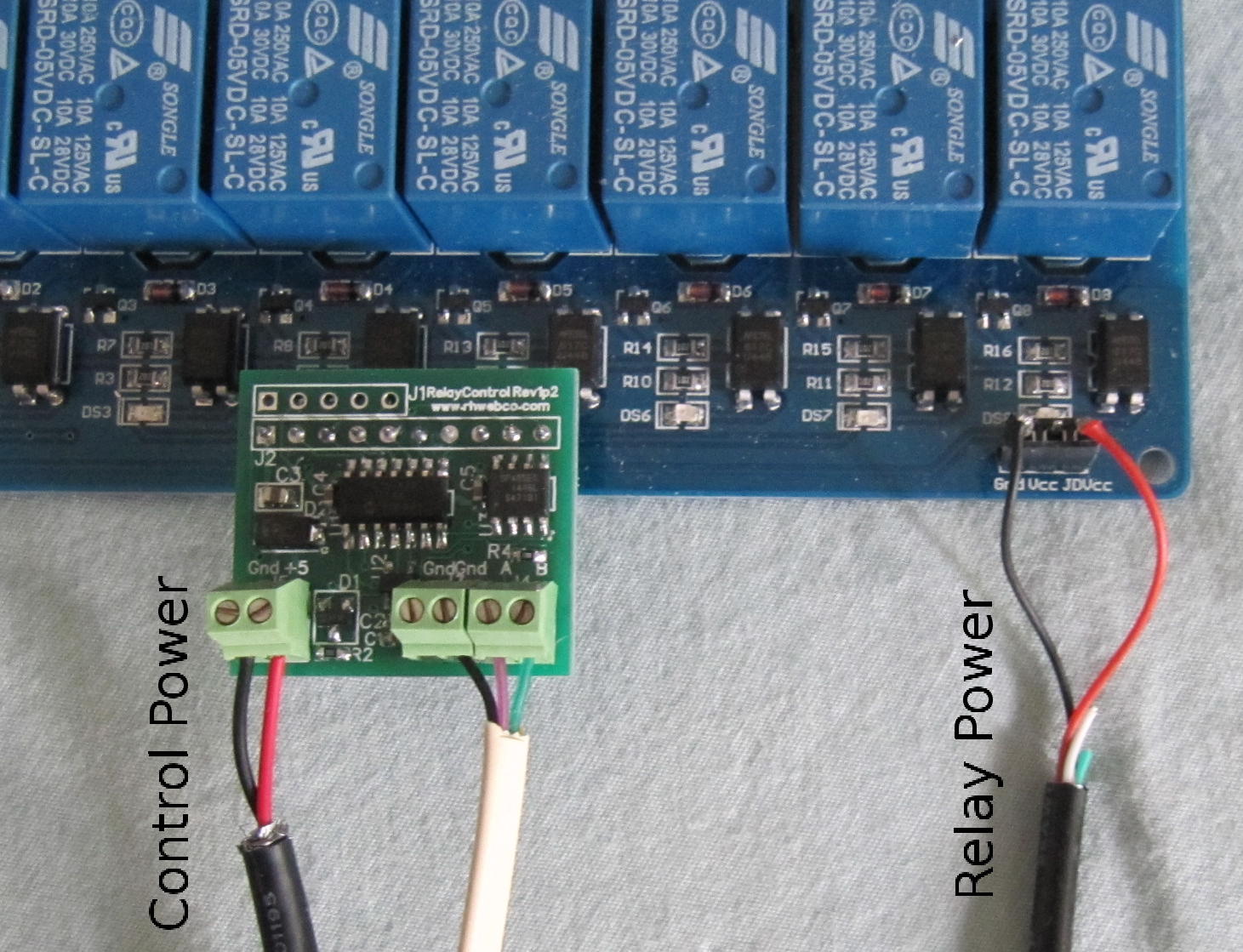
This relay driver board will turn all of the relays off when the power is first applied. Note that the voltage level required to turn off a relay is a high (5v). If there is a long transient in the 5v power supply, this board may turn off all of the relays. There is a read command that the host may use in order to check to make sure that this has not happened. The state of the relays may be read and compared to what was set, if they are different due to a power outage, the host will need to re-send the command to set the relays. The chances of this happening may be much reduced by using a separate 5v supply for the control boards. The relay boards come with the option of using a separate supply for the relays. Opto-isolation devices are provided on the relay board, but the Gnd-Vcc-JDVcc connector must be properly connected in order to make them useful. I recommend using this option – especially when there are many units connected together. This is the configuration shown on the picture of the control board plugged into the relay board. Standard USB power adapters may be used If the voltage is measured to be between 4.75 and 5.25 volts. The adapter for the relay board power should be rated for 1 amp. One adapter can power a few relay boards. The adapter for the control board power may be one of the less expensive ones that are rated for 500 Milli-amps, but the voltage must not be higher than 5.25v. One adapter can power many relay control boards.
Before connecting multiple boards together, each board should be connected to the host and the host should send the set address command. This address will be stored inside of the relay control board even after the power has been turned off. When multiple boards have been connected together, each board will only respond to commands that have the address that was set.
The relay control board was set to address 01 before shipment.
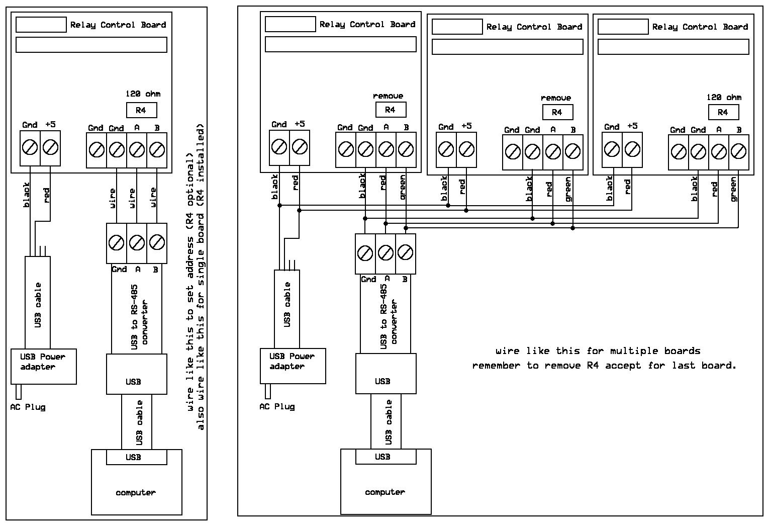
For single board: R4 is fine as it was shipped. This was factory installed with a 120 ohm resistor.
For multiple boards: R4 should be removed from all boards that are connected to the same converter, accept for the last board (farthest away from the host). R4 should be 120 ohms on the last unit and it is a 0603 package.
The baud rate is 9600, 8 bits, no parity, 1 stop bit. The controller should wait up to 50 milliseconds for the response to be received.
All commands consist of ASCII standard characters and numbers, accept for the beginning and the end. The beginning of a command is the ASCII '[' and the end is the ']'. The address will be the second and third character. The set address must consist of ASCII numbers and/or the letters A through F (case is ignored).
All commands begin with [ and end with ]
(CR and LF will be ignored)
Format is [02R00] where 02 is address and R is the command. The following commands are supported:
A = set address
R = read
W = write
address 00 will be used to set the device address.
command [00A03] will set all connected units to address 03. This command should only be used when a single unit is connected. The 03 (device address) may be 00 through FF.
This relay driver board has commands that allow the 8 relays to be set as a single 8 bit byte, or individually by relay number.
Example commands:
[00A01] set device address to 01 (this was the address when it was shipped).
[01R08] read output byte. This will return the state of all relays at once
[01W0801] write output byte (data is 01). This will set the state of all relays at once (00 through FF).
The following commands may also be used:
[01R00] read output bit 0
[01R01] read output bit 1
[01R02] read output bit 2
[01R03] read output bit 3
[01R04] read output bit 4
[01R05] read output bit 5
[01R06] read output bit 6
[01R07] read output bit 7
example of the return for [01R01] is: [R0001] if relay 1 is on.
[01W0001] set relay 0 on
[01W0000] set relay 0 off
[01W0101] set relay 1 on
[01W0100] set relay 1 off
[01W0201] set relay 2 on
[01W0200] set relay 2 off
[01W0301] set relay 3 on
[01W0300] set relay 3 off
[01W0401] set relay 4 on
[01W0400] set relay 4 off
[01W0501] set relay 5 on
[01W0500] set relay 5 off
[01W0601] set relay 6 on
[01W0600] set relay 6 off
[01W0701] set relay 7 on
[01W0700] set relay 7 off
Example of the return for [01W0101] would be [W00AA] if every other relay is on ( 10101010, or 0xAA ). The state of all relays will be returned, even though the command is to set only a single relay.
If the command [00A18] was sent (to set the device address to 18), relay 2 on device 18 could be set with [18W0201].
The output will go low when set to a 1 and the relay will turn on. In other words, the output port from the relay Control board will seem to be inverted from the byte that is sent, but a 1 will turn on the relay and a 0 will turn off the relay.
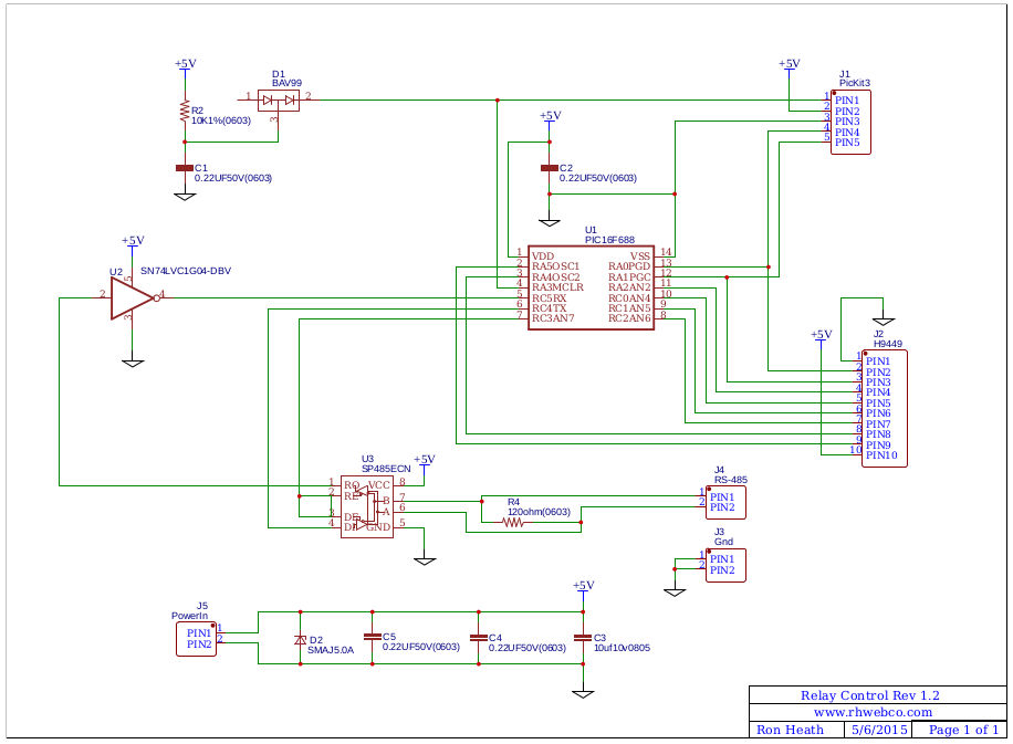
The schematic for the relay control board: